The hardware and bandwidth for this mirror is donated by METANET, the Webhosting and Full Service-Cloud Provider.
If you wish to report a bug, or if you are interested in having us mirror your free-software or open-source project, please feel free to contact us at mirror[@]metanet.ch.
Let's try something more exciting. Sketch has no notion of a
solid,
but polygonal faces
can be used to represent the
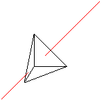
boundary of a solid. To the previous example, let's add three more
triangular polygons to make the faces of an irregular tetrahedron.
  % vertices of the tetrahedron
  def p1 (0,0,1) def p2 (1,0,0)
  def p3 (0,1,0) def p4 (-.3,-.5,-.8)

  % faces of the tetrahedron.
  polygon(p1)(p2)(p3) % original front polygon
  polygon(p1)(p4)(p2) % bottom
  polygon(p1)(p3)(p4) % left
  polygon(p3)(p2)(p4) % rear

  % line to pierce the tetrahedron
  line[linecolor=red](-1,-1,-1)(2,2,2)
This example uses definitions, which begin with
def.
These define or give names to points,
which are then available
as references
by enclosing the names in parentheses,
e.g. (foo).
The parentheses denote that the names refer to points; they are
required. There can be no
white space between them and the name.
As you can see, comments
start with % as in TeX and extend
to the end of the line (though # will work as well). White
space,
including spaces, tabs and blank lines, has no effect in the sketch
language.
If we look inside the TeX file produced by sketch, there
will be only three polygons. The fourth has been
culled because it is
a “back face”
of the tetrahedron, invisible to our view. It is
unnecessary, and so it is removed.
In some drawings, polygons act as zero-thickness solid surfaces with
both sides visible rather than as the faces of solid objects, where
back faces can be culled. For zero-thickness solids, culling
is a
problem. One solution is to use a pair of sketch polygons for
each zero-thickness face, identical except with opposite vertex
orders. This is unwieldy and expensive. A better way is to
set the sketch internal option cull to false in
the usual PSTricks manner.
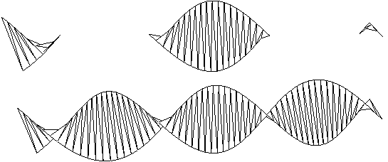
polygon[cull=false](p1)(p2)(p3)The following shows the same helix shape drawn first with cull=true (the default) and then cull=false.
We'll soon see how to produce these helixes with a few lines
of sketch language code.
It may be tempting to turn culling off gratuitously so that vertex order
can be ignored. This is not a good idea because output file size and
TeX and Postscript processing time both depend on the number of
output polygons. Culling usually improves performance by a factor of
two. On the other hand, globally setting cull=false is
reasonable while debugging. See Global options and
Limits on error detection.
These binaries (installable software) and packages are in development.
They may not be fully stable and should be used with caution. We make no claims about them.